Square Electrical Box Injection Mold 3d+cad Drawings
 AutoCAD-ZWCAD - Free Download")
 AutoCAD-ZWCAD - Free Download")
 AutoCAD-ZWCAD - Free Download")
 AutoCAD-ZWCAD - Free Download")
 AutoCAD-ZWCAD - Free Download")
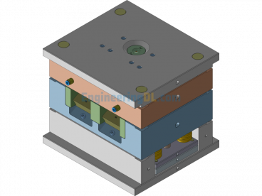
This mold is a 3D and 2D design of an injection mold for a square electrical box. The mold uses a three-plate mold base and a pinpoint gate for injection, with a side core-pulling mechanism.
The motion of the injection mold for opening and closing is briefly introduced:
Opening the mold: After the injection machine completes the injection, holding pressure, and cooling process, the next step is to open the injection mold. The power to open the mold comes from the hydraulic cylinder at the rear part of the injection machine. When the injection control system issues the mold opening command, the hydraulic cylinder starts working, driving the rear plate of the injection to move. Since the moving part of the injection mold is fixed on the rear plate of the injection machine, it will move backward along with it. The fixed part of the mold is stationary and remains fixed at the front. However, this is a double parting plane mold base structure, where the cavity fixed plate needs to move.
Therefore, when opening the mold:
1. The first parting happens, with the cavity fixed plate separating from the stripper plate. The power for this movement comes from the nylon plug mechanism installed between the moving mold fixing plate and the fixed mold fixing plate. Under its frictional influence, the movement reaches a specified distance, which is the total length of the runner. Since the slider is fixed on the fixed mold plate, and the inclined pin is fixed on the panel, the slider relative to the inclined pin also moves a certain distance due to the inclined pin’s action, simultaneously generating a side core-pulling movement. The limit mechanism for the pulling distance employs limiting screws.
2. The second parting follows, continuing the mold opening movement based on the first parting. At this point, the stripper plate begins to move. The stripper plate’s function is to forcibly separate the runner from the gate ejection rod. This movement distance is generally sufficient between 8mm and 10mm. As with the first mold opening, the hook and inclined pin do not completely separate, continuing the side core-pulling and completing the core-pulling action. Limiting screws are also used for control. The purpose of the first two partings is to create space in the mold, allowing the runner to be removed.
3. The third parting happens last, where continuing the mold opening separates the moving and fixed mold at the parting surface. Once the moving mold reaches the specified position of the injection machine, there will be sufficient space for the product to be ejected. At this time, the ejection cylinder installed behind the injection machine begins to work upon receiving the command, performing an ejection motion forward. The round rod attached to the ejection cylinder pushes the ejector pin fixing plate forward, with the ejector pin directly acting on the inner surface of the plastic product, pushing the product out of the moving mold core. The product can be picked and placed into a designated box either by a robot arm installed on the top of the injection machine or manually by an operator. This completes the entire mold opening operation of the injection mold.
Closing the mold: After the product is removed, the injection process proceeds to close the mold. The power to close the mold also comes from the hydraulic cylinder at the rear part of the injection machine. When the injection control system issues the mold closing command, the hydraulic cylinder starts working, driving the rear plate of the injection to move forward. The moving part of the injection mold moves forward together with the injection rear plate. When the inclined surface of the inclined pin contacts the inclined surface of the slider, the slider resets. When the reset rod of the moving mold touches the fixed mold fixing plate, it drives the ejector pin fixing plate and the ejector pin to reset. The moving mold continues to move forward to the specified position until the parting surfaces of the moving and fixed molds tightly fit together, completing the entire mold closing operation.
Specification: Square Electrical Box Injection Mold 3d+cad Drawings
|
User Reviews
Be the first to review “Square Electrical Box Injection Mold 3d+cad Drawings”
You must be logged in to post a review.


There are no reviews yet.