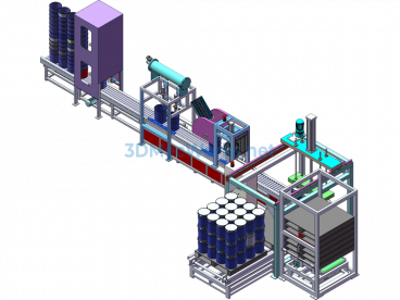
Rp High-Power Plastic-Sealed Motor Assembly Automated Production Line


RP High-Power Plastic Sealing Motor Assembly Processing Line Automation Line Complex Equipment – Original Drawings (With Complete Engineering Drawings). One side of the entire line body is equipped with a drag trough for the motor power line, which is made of SUS304 stainless steel, requiring the entire length to be smooth. The line body drags the power line to move in the trough without causing any mechanical damage to the power line. The setting of this trough should allow the stator power line, brought by the double-station automatic press-in machine, to automatically enter without causing damage to the power line. The line body power line and air pipe are not mixed together, and are encapsulated with a dedicated wire trough. For maintenance and convenience, the lights, fans, and socket main power live and neutral wires must be controlled separately with 2P leakage protection switches. Every 10 lights have a small switch on the lamp holder for control. The three-phase socket wiring is independent, and there are two mains sockets every 1.5 meters under the line body. There is an air source triplet and a 1-inch solenoid valve at the main air source interface for control (the control line can be shared with the main switch of the lights).
This RP high-power plastic sealing motor assembly processing assembly line is suitable for the manual and automatic mixed assembly of high-power plastic sealing motors.
1. Function: Suitable for 95 and 110 high-power plastic sealing motor series (the motor shaft is single-sided shaft extension, the maximum shaft length is 150mm from the end cover to the shaft head, see the motor outline drawing for details) for manual and automatic special machine mixed assembly; The motor is installed on the fixture board vertically with the shaft head facing up.
2. Working Principle and Action Sequence:
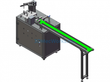
A. The special fixture board enters the fixture board storage area from the lifting platform.
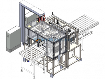
B. When the storage area for placing BMC stators is empty, the fixture board enters this station from the storage area. (The stopper blocks the fixture board, and the fixture board stops, same as below) The manipulator places the BMC stator (a total of 2 sets) in the corresponding position of the special fixture board, steps on the foot switch, the fixture board descends, and enters the next storage area.
C. When the storage station for placing the rotor, PG board, and BB cover is empty, the fixture board automatically enters this station, and then steps on the foot switch, the fixture board automatically runs to the next temporary storage station.
D. When the storage station for pressing the BB cover is empty, the fixture board automatically enters this station to automatically press the BB cover and detect the displacement amount, etc. After pressing, step on the foot switch, and the fixture board automatically runs to the next temporary storage station.
E. When the performance testing station is empty, the fixture board automatically runs to this station for manual performance testing. After the performance testing is completed, step on the foot switch, and the fixture board automatically runs to the fixture board lifting platform storage area.
F. Execute the next cycle.
3. The total length of the line is 5.5 meters (including the lifting platforms at both ends), and the total width is 300mm (excluding the protruding parts of the lifting platforms at both ends). The height of the upper layer including the fixture board is 800 mm, and the height between the two layers is 400mm. The height of the supporting legs of the line body is adjustable, with an adjustment range of ±30mm.
4. The line body adopts a double-layer return board structure, the upper layer is for motor transmission, and the lower layer is for quick return of the fixture board.
a. The line body uses roller chain transmission, with independent power drive.
b. The lower layer of the line body as a whole uses roller chain transmission.
c. The frame of the line body is made of high-strength aluminum alloy profiles, with a total load-bearing capacity of 300kg/1000mm. Along the total length of the line, the side bending should not exceed 5mm, and the upward and downward warping should not exceed 5mm.
d. The line body can accept the control signals sent by each process special machine and generate corresponding process actions.
5. The upper and lower chain systems should use independent power systems, and the lower return board speed should be 20% higher than the upper layer speed. The chain speed of the upper and lower layers is adjustable, with an adjustment range of 0-15m/min.
6. The design of the fixture board should fully consider the impact and collision. There should be no contact between metal surfaces when the fixture board is in the running and stopping state. In any area of the line body, at the workstation where manual parts are placed, and in the section where parts may fall into the chain, protective covers should be added above the upper and lower chains.
Specification: Rp High-Power Plastic-Sealed Motor Assembly Automated Production Line
|
User Reviews
Be the first to review “Rp High-Power Plastic-Sealed Motor Assembly Automated Production Line”
You must be logged in to post a review.


There are no reviews yet.