Precision Variable Seeder, No-Till Fertilizing Planter for Corn


The technical solution of the invention will be described in detail and exemplified in conjunction with the following drawings to explain its workflow.
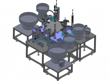
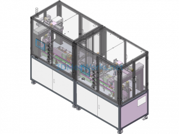
As shown in Figure 1, this is a front view of the precision corn seeding and variable fertilization machine; it includes 1. Seeding quality controller, 2. Fertilizer box, 3. Fertilization device, 5. Seeding soil covering wheel, 6. Seeding drive ground wheel, 7. Seeding and fertilizing machine frame, and 8. Row marker. The fertilizer box 2 is located above the seeding and fertilizing machine frame 7, with the fertilization device 3 connected below. The row marker 8 is connected to the seeding and fertilizing machine frame 7; each fertilizer box 2 is equipped with a material level detection sensor 12 for detecting the status of the material inside the box; the seeding quality controller 1 is installed at the front end of the fertilizer box.
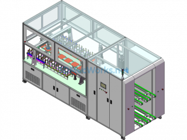
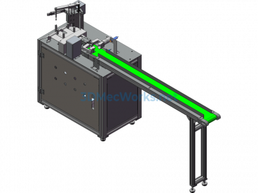
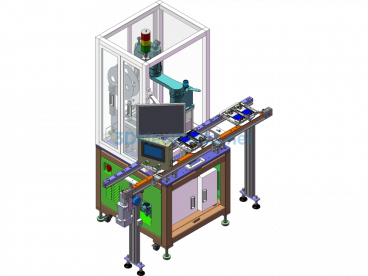
Further reference to Figures 2 and 3 illustrates the relative positional relationships; Figures 2 and 3 include 9. Grass divider assembly, 10. Fertilizer opener, 11. Servo drive motor, 12. Material level monitoring sensor, 13. Seed box, 14. Supplementary fertilizer box, 15. Supplementary fertilizer soil covering wheel, and 16. Seeding mechanism assembly; the seeding drive ground wheel 6 is located in the middle of the seeding and fertilizing machine frame 7, and there are four fertilizer openers 10 symmetrically distributed below the frame; four grass divider assemblies 9 are located behind each fertilizer opener 10 and are connected to the seeding and fertilizing machine frame 7; the rear end of the frame is sequentially connected to the seeding mechanism assembly 16 and the supplementary fertilizer mechanism. The installation positions of the Omron proximity speed switch 18 and the capacitive fertilizer blockage sensor 23 refer to Figures 4 and 5; the fertilization vehicle terminal 21 and the seeding vehicle terminal 22 are located at the front end of the tractor cab as shown in Figure 6, and are connected to the controller on the seeder via the CAN bus protocol.
Precision seeding control implementation method:
In the seeding mechanism assembly, a photoelectric sensor is installed on the side wall of the seed discharge tube to detect the seeding status; at the same time, the Omron proximity speed switch 18 detects the rotation speed of the drive shaft speed measuring gear 20; the measurement signals of both are transmitted to the seeding quality controller 1 for analysis. The Omron proximity speed switch 18 analyzes the theoretical seeding status, and the photoelectric sensor signal analyzes the actual seeding status. The two are compared and analyzed to determine whether there is missed seeding and the amount of missed seeding. Combined with the vehicle-mounted GPS system, the position of missed seeding can be recorded in real time, and the work information is transmitted to the seeding vehicle terminal 21 via the CAN bus protocol to generate relevant technical documents, store and display the seeding status; this facilitates subsequent intelligent missed seeding replanting operations, realizing precision seeding control; at the same time, the seed box 14 is equipped with a material level sensor to monitor the seed status in real time, which is transmitted to the vehicle-mounted seeding terminal 22 for display, providing a seed shortage warning for the driver.
Variable fertilization control method:
This invention uses a no-till corn fertilizing and seeding machine, which requires two fertilization processes during seeding: one is deep fertilization and the other is surface supplementary fertilization. During fertilization, a capacitive fertilizer blockage sensor 23 is installed on the side wall of each fertilizer tube 22 to detect the blockage status of the fertilizer and the actual fertilization rate. If there is a blockage or the fertilization rate does not match the set rate, an alarm will be triggered on the fertilization vehicle terminal 21; in addition, the fertilization quality controller 4 is used to drive and control the speed of the servo motor 11 to control the fertilization rate to meet the requirements. Each fertilizer box 3 and supplementary fertilizer box 15 is equipped with a material level monitoring sensor 12 to detect the amount of fertilizer and provide fertilizer shortage warnings. Using the existing information on the required amount of fertilizer for the land, combined with the GPS module in the fertilization vehicle terminal 22 to obtain latitude and longitude information and machine operating speed, the fertilization amount at the current machine position is determined; the data acquisition module in the terminal collects and processes the data provided by the sensors, including the amount of material discharged, drive shaft rotation speed, DC servo motor speed, blockage and fertilizer shortage information, as well as GPS and other sensor information; the fertilization quality control system in the terminal generates fertilization decisions based on the information collected by the data acquisition module from each sensor and sends them in real time to the fertilization quality controller 4, realizing precise fertilization at the current position of the machine. Operating speed, latitude and longitude information, current fertilization amount, current discharge amount, and blockage and other operating parameters are displayed in real time through the fertilization vehicle terminal; thus, variable fertilization control is achieved.
(This invention patent was designed by myself as a student at the time, hoping to help friends in need)
Specification: Precision Variable Seeder, No-Till Fertilizing Planter for Corn
|
User Reviews
Be the first to review “Precision Variable Seeder, No-Till Fertilizing Planter for Corn”
You must be logged in to post a review.


There are no reviews yet.