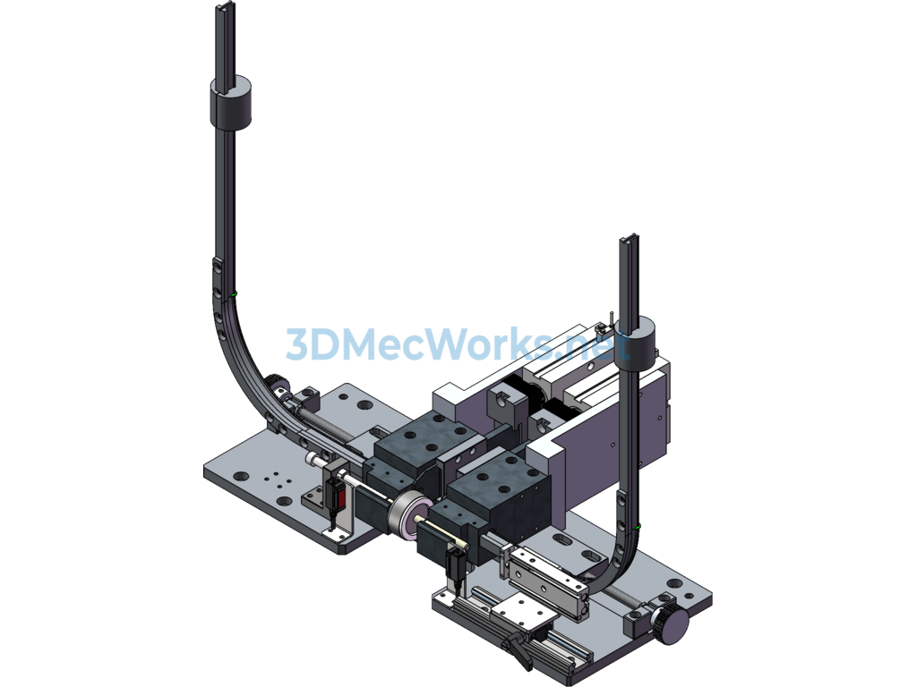
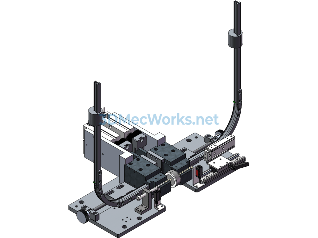
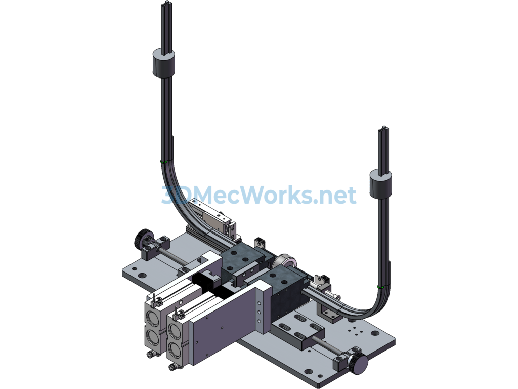
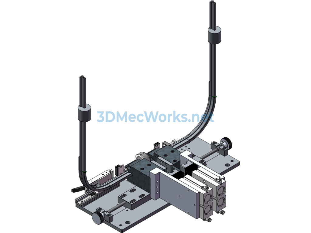
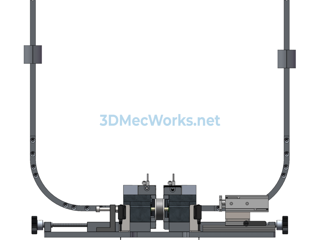
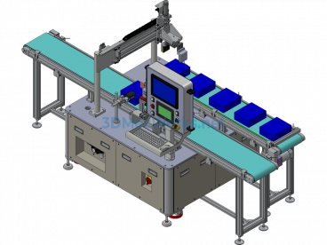
The model of the circlip machine in this set is used as an assembly fixture for the retaining ring at the bearing position of a micro motor rotor. It is used in a stage of rotor processing in motor manufacturing. After the rotor is press-fitted onto the shaft, the E-type circlip is pressed into the circlip groove using the fixture.
After multiple optimizations, the manufacturability of the rotor circlip guide part in this structure has been greatly improved, and the processing cost has been reduced by 50%. The arc segment of the guide bar is processed using a lathe and then assembled into an integrated guide bar. This avoids excessive thickness of wire-cut parts and subsequent bending processes, reducing complexity and ensuring smoother circlip performance.
Integrating the advancement cylinder into the circlip fixing base facilitates model switching on the production line.
Specification: Micro Motor Rotor Snap Ring Fixture
|
User Reviews
Be the first to review “Micro Motor Rotor Snap Ring Fixture”
You must be logged in to post a review.




There are no reviews yet.