Fpc Flexible Circuit Board Automation Steel Press Design (3d Documents + Keyshot Rendering Files)
 - SolidWorks - Free Download")
 - SolidWorks - Free Download")
 - SolidWorks - Free Download")
 - SolidWorks - Free Download")
 - SolidWorks - Free Download")
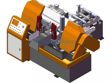
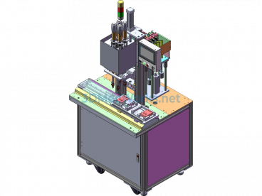
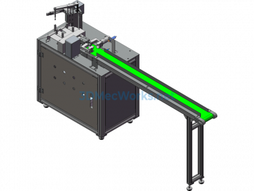
Automatic steel pressing design scheme for FPC flexible board, designed with SolidWorks2014, including detailed 3D models, STEP files, and Keyshot rendering files. Features are not included, can be edited and modified. The mechanism is complex, with a decompressed size close to 0.98 GB and a total of more than 310 parts. Automatic steel pressing design for FPC flexible boards (3D documents + Keyshot rendering files). Structure of a single-layer FPC flexible board: This structure represents the simplest form of flexible boards. Typically, the base material + transparent adhesive + copper foil is a set of purchased raw materials, and the protective film + transparent adhesive is another set of purchased raw materials. First, the copper foil undergoes etching and other process treatments to create the required circuits, and the protective film is drilled to expose the corresponding pads. After cleaning, they are combined using a rolling method. Then, the exposed pad sections are plated with gold or tin for protection. In this way, the large board is completed. Generally, the large board is then stamped into smaller circuit boards of the required shape. There are also cases where no protective film is used and a solder resist layer is directly printed on the copper foil. This makes the cost lower, but the mechanical strength of the circuit board will be compromised. Unless the requirement for strength is low but the price needs to be as low as possible, using a protective film method is recommended.
Specification: Fpc Flexible Circuit Board Automation Steel Press Design (3d Documents + Keyshot Rendering Files)
|
User Reviews
Be the first to review “Fpc Flexible Circuit Board Automation Steel Press Design (3d Documents + Keyshot Rendering Files)”
You must be logged in to post a review.


There are no reviews yet.