Design Model of Automatic Processing Line for Brake Disc Truss


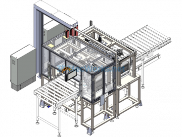
Automatic Brake Disc Processing Line Gantry, the gantry robot has 3 servo axes: respectively the X axis, Z1 axis, and Z2 axis, equipped with two symmetrically arranged fingers. The entire machine is composed of a support structure, gantry robot, loading bin, unloading bin, flipping washer, angular positioning machine, manual inspection line, reverser, and air cleaning system, etc.
The support structure includes pillar profiles, safety nets, adjustment mechanisms, manual ladders, etc.;
The robot section includes the X-axis drive system, Z1-axis drive system, Z2-axis drive system, robotic arm, clamping mechanism, clamping fingers, etc.;
The loading bin contains a conveying system, positioning system, stop system, etc.;
The unloading bin contains a conveying system, stop system, etc.;
The reverser includes a positioning system, clamping system, flipping system, etc.;
The angular positioning machine includes a detection system, and rotation system, etc.;
The manual inspection line includes a storage system, positioning system, inspection system, etc.;
The coolant dumping system includes a flipping system, filtering and recycling system, etc.; the air cleaning system includes a high-pressure washing system, filtering recycling system, flipping system, high-pressure air cleaning system, etc.
Specification: Design Model of Automatic Processing Line for Brake Disc Truss
|
User Reviews
Be the first to review “Design Model of Automatic Processing Line for Brake Disc Truss”
You must be logged in to post a review.


There are no reviews yet.