Material: 08 Steel
Material Thickness: 2.0mm
Batch: Large Batch
Unspecified Dimension Tolerance: IT6
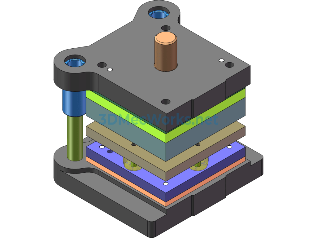
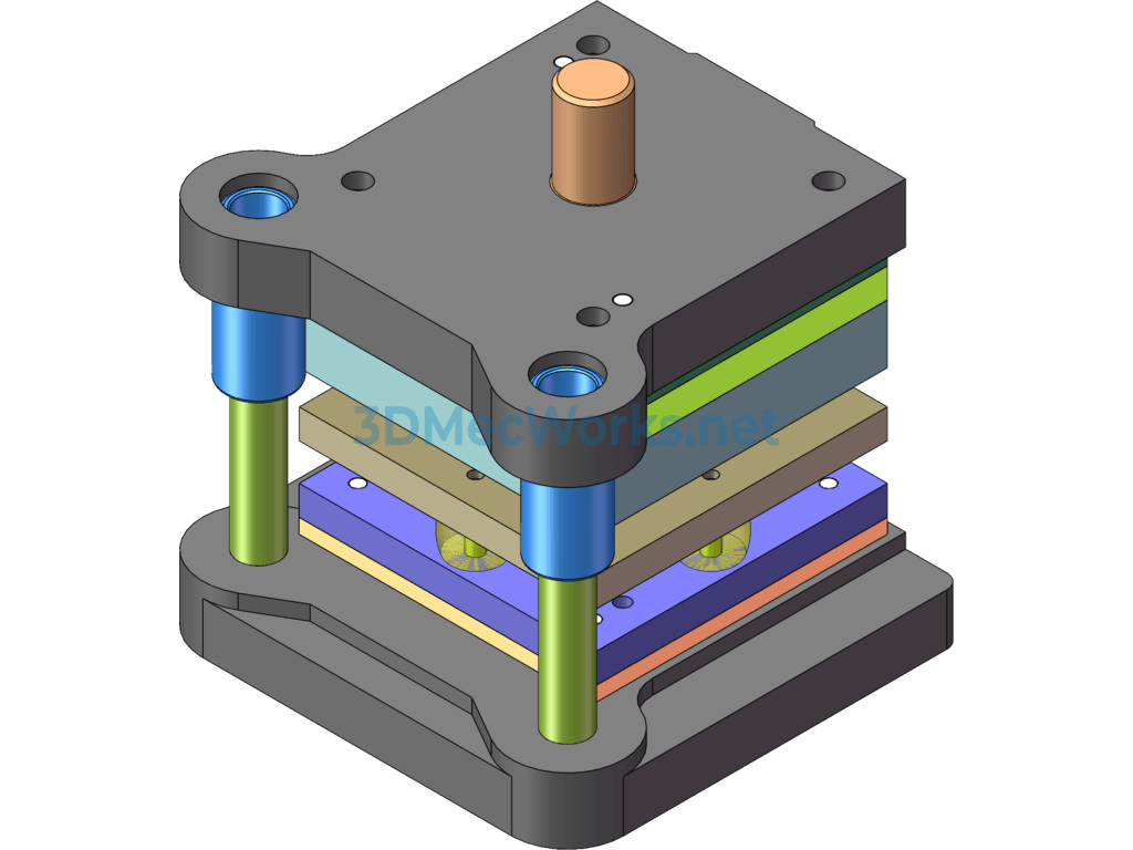
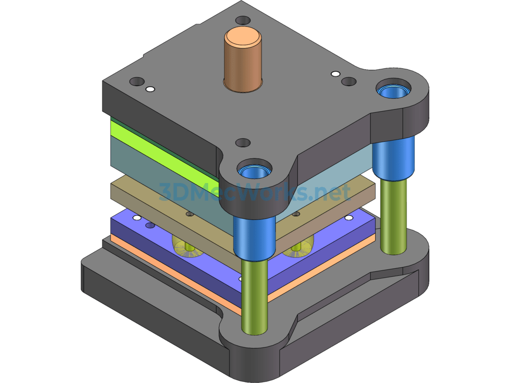
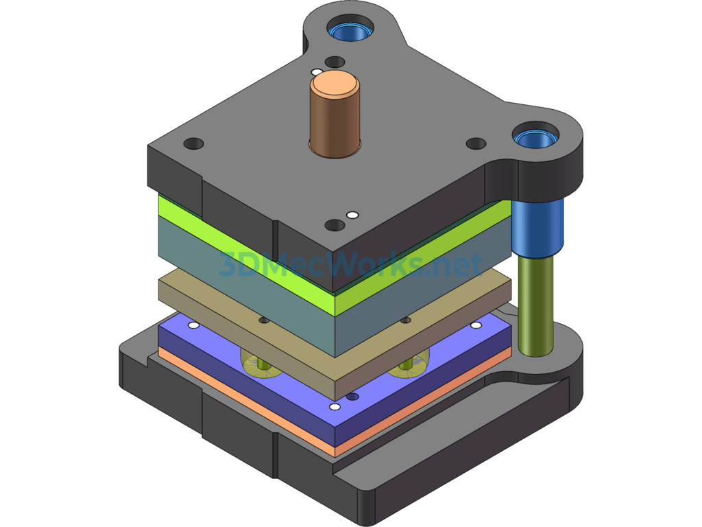
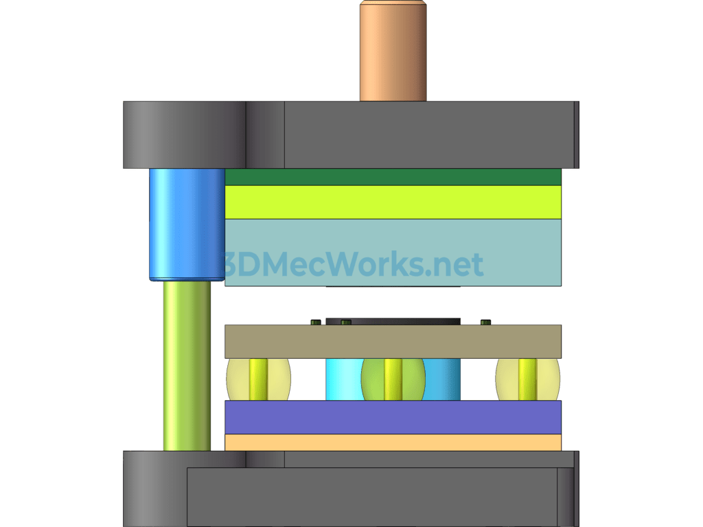
This set of molds is for composite electrical contact pieces. The drawings include CAD assembly and part diagrams, UG 3D diagrams, and the components of the drawings are complete and drawn according to standards.
1. The punch is installed using a press-fit method. First, grind the punch flat before connecting it with the backing plate.
2. The guide sleeve and the guide post have a clearance fit of H7/h6. When pressing in, pay attention to correcting the guide post and ensuring the perpendicularity of the guide sleeve with the template. The fixed end surface distance of the assembled guide post and the guide sleeve from the plane of the upper and lower mold bases is 1~3mm.
3. The guide post and the lower mold base have an interference fit of H7/r6; the guide sleeve and the upper mold base have an H7/r6 fit.
Specification: Composite Mold Design for Electrical Connection Tabs
|
User Reviews
Be the first to review “Composite Mold Design for Electrical Connection Tabs”
You must be logged in to post a review.




There are no reviews yet.