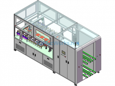
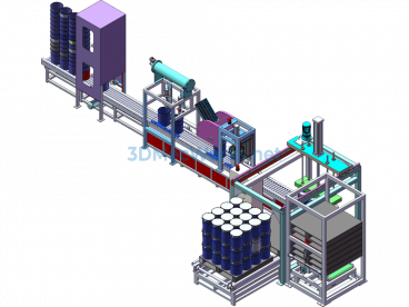
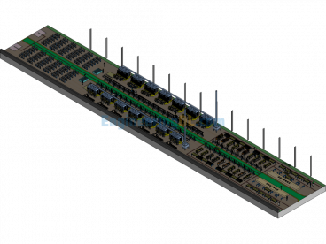
Automated Press-Fit Snap Ring Retaining Shaft Assembly Machine Op170 & Op180


OP170 & OP180
1. Purpose: Manual installation of lower retaining ring, manual oil application on upper column pipe; automatic assembly of rubber cushion, automatic pressing of the upper column pipe, automatic shaft pulling, pressing of the upper retaining ring.
2. Compatible Products: A13TE, ZTM11E, FE-3DA
3. Equipment Operation Process (50s)
STA0 (28s)
1. Take the upper column pipe and place it on the oiling station for automatic oiling (manual 2s)
2. Place the gearbox assembly into the retaining ring installation fixture, manually install the retaining ring (manual 14s)
3. Place the oiled upper column pipe into the automatic equipment after scanning (manual 6s)
4. Place the workpiece with the installed lower retaining ring into the automatic equipment after scanning (manual 6s)
STA1 (17s)
1. Manual material feeding (manual 3s)
2. Place the column assembly into the lower fixture on the rotary table (manual 3s)
3. Take the oiled upper column, release the handle, and place it on the positioning fixture (manual 4s)
4. Phase tightening cylinder presses the adjustment bracket (automatic 1s)
5. Column pushing cylinder straightens the tilted column (due to spring force pulling it slant) (automatic 1s)
6. Axial positioning pneumatic gripper clamps the upper column (automatic 1s)
7. Take another upper column and place it into the oiling fixture (manual 3s)
8. Press the start button (manual 1s)
9. The upper column transfer mechanism moves the upper column to the middle waiting position (2s)
STA2 (8s)
1. Pressure plate cylinder extends (1s)
2. Confirm press cylinder extends, press the steering shaft to the bottom (2s)
3. Pressure plate cylinder retracts (1s)
4. Confirm press cylinder retracts (2s)
5. Visual inspection to see if the lower retaining ring is installed correctly (2s)
STA3 (13s)
1. Cushion grasping mechanism inserts the cushion into the steering shaft (6s)
2. Cylinder presses down to seat the cushion in place (5s)
3. Camera checks if the cushion assembly is correct (2s)
STA4 (23s)
1. The upper column transfer mechanism moves the upper column under the servo press (automatic 2s)
2. The lower support mechanism extends to support the lower fixture (1s)
3. Servo press pushes down, pressing the upper column into the column assembly (11s)
4. The lower fixture positioning support mechanism retracts (2s)
5. Servo press returns to the initial position (3s)
6. The upper column transfer mechanism moves the upper column to STA1 (4s)
STA5 (24s)
1. Servo electric cylinder descends (2s)
2. Tighten the servo rotation to fit the guide sleeve onto the input shaft (2s)
3. The retaining ring feeding mechanism sends a retaining ring to the guide sleeve (7s)
4. Push cylinder releases push gripper (1s)
5. Gripper cylinder re-grips guide sleeve (1s)
6. Servo electric cylinder rises, pulling the guide sleeve to press the retaining ring into the groove (4s)
7. Tighten the servo rotation to remove the guide sleeve (2s)
8. Servo electric cylinder rises to lift the guide sleeve (2s)
9. Lift cylinder retracts (2s)
Specification: Automated Press-Fit Snap Ring Retaining Shaft Assembly Machine Op170 & Op180
|
User Reviews
Be the first to review “Automated Press-Fit Snap Ring Retaining Shaft Assembly Machine Op170 & Op180”
You must be logged in to post a review.


There are no reviews yet.