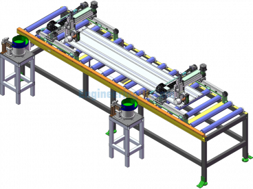
A Rear Shell Jig (fourth Series)
 - Exported - Free Download")
 - Exported - Free Download")
 - Exported - Free Download")
 - Exported - Free Download")
 - Exported - Free Download")
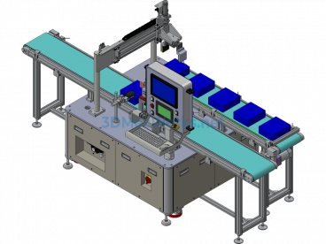
Fourth Operation: Equipment used: VMC850 (same as the first operation)
Part to be processed: After mounting the other half of the bearing bush on the E reference surface, process the C and D reference holes, end face, and boss surface-related features.
Clamping principle:
Using the installation joint surface processed in the first operation as the clamping surface, center using the two 2-φ8 pin holes in the F-F view, with one side and two pins.
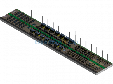
Plan requirements:
Process two pieces in one clamping:
First piece (first station) processes the C reference and related features; second piece (second station) processes the D reference and related features, bore the C and D references (bearing bush holes) in one pass, ensuring the tool does not interfere in the middle cavity.
Specification: A Rear Shell Jig (fourth Series)
|
User Reviews
Be the first to review “A Rear Shell Jig (fourth Series)”
You must be logged in to post a review.


There are no reviews yet.