D077 Instrument Panel Punching Equipment


Instrument Panel Punching Machine Catalog
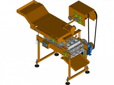
I. Overview 1
II. Main Technical Parameters 1
2.1 Overall Parameters 1
2.2 Working Environment 1
III. Equipment Composition 1
3.1 Mechanical Part 1
3.2 Pneumatic System 2
3.3 Electrical System 3
IV. Operation and Use 3
4.1 Operating Preparation…3
4.2 Electrical Operation…3
4.3 Manual Mode…4
4.4 Automatic Mode…5
4.5 Parameter Setting…6
V. Operating Procedures 6
VI. Maintenance and Repair 6
6.1 Maintenance and Repair of Mechanical Parts 7
6.2 Maintenance and Repair of Pneumatic System 7
6.3 Maintenance and Repair of Control System 7
VII. Installation Instructions 7
VIII. Accessories/Wear Parts/Spare Parts 7
IX. Provided Information 8
X. Appendix (Electrical Schematic)…8
I. Overview
This equipment is used in the production workshop, mainly suitable for the punching of the two-sided ventilation holes and the front wiring harness holes of the D077 product. Except for the D077 product, this equipment is not suitable for other products. The punching work is automatic, and the drilling work is semi-automatic.
II. Main Technical Parameters
2.1 Overall Parameters
Equipment Model: ZKBC-WL-001
Maximum Dimensions: 2900mm×1650mm×2200mm (L×W×H)
Total Weight: About 4.5 t
Motor Power: 2.5 kW
Max Output Force of Hydraulic Cylinder: 10t
Heating Temperature: Less than 60℃
Production Cycle: 110 seconds/piece
Noise: ≤60db
2.2 Working Environment
Power Supply Voltage: AC220V±10%; 50Hz±2%
Relative Humidity: ≤95%RH
Working Temperature: 0~40℃
Compressed Air Pressure: 0.6MPa
III. Equipment Composition
The main components of this equipment can be divided into mechanical part, pneumatic system, and electrical system.
3.1 Mechanical Part
The equipment mainly consists of base, servo motion system, positioning mechanism, punching system, temperature control system, and drilling mechanism.
3.1.1 Base
The base is made of 120×120 square steel pipes and 50mm thick iron plates welded together, which can withstand greater external forces and ensure that the equipment does not deform during punching and use. The base uses adjustable foot supports, with an adjustable height of 100mm.
3.1.2 Servo Motion System
The servo motion system mainly consists of servo motor, ball screw, fixture, and clamping cylinder. The servo motor is connected to the ball screw using a coupling, and the motion accuracy of the moving part can reach 0.015mm. The fixture is equipped with a sensor to detect the presence of the product. The equipment cannot be started without the product installed, and when the product is placed, it must be ensured that each positioning point is accurately positioned to avoid interference with other parts during movement.
3.1.3 Positioning Mechanism
The positioning mechanism includes two ejection cylinders and positioning sleeves and pins installed on the equipment base. It serves to secondary position the fixture and bear the lateral shear stress of the system, improving the positioning accuracy of the fixture and protecting the linear guide and ball screw.
3.1.4 Punching System
The punching system is the main part of the equipment for punching, which includes two separate parts on the left and right, fixed on the equipment base by a gantry beam. Each part includes a hydraulic intensifier cylinder, floating joint assembly, guide post, guide sleeve, and punch.
3.1.5 Temperature Control System
The temperature control system consists of a heating plate, heating rod, and temperature sensor. The heating system is used to heat the punch, changing from cold cutting to hot cutting to reduce burrs. The heating system’s temperature is less than 60℃, and the temperature sensor’s resolution is 0.1℃.
3.1.6 Drilling Mechanism
The drilling mechanism is designed as semi-automatic, including rodless cylinders, linear guides, pneumatic drills, linear bearings, and buffers. The lateral movement of the mechanism is automatic, and the drilling action is manual.
3.2 Pneumatic System
The pneumatic system mainly controls and positions the equipment. The air source processing part includes filtering, oil-water separation, and pressure adjustment functions. The control part mainly consists of electromagnetic reversing valves, centrally controlled by a programmable logic controller (PLC), allowing users to control the actions of the executive components through operation buttons. The executive components are cylinders, which realize functions such as positioning and punching through their movement.
3.3 Electrical System
This system consists of servo motors, servo controllers, PLC, etc., controlled by PLC. For details, please refer to the electrical schematic and program flowchart.
IV. Operation and Use
4.1 Operating Preparation:
1) Check whether all kinds of components in the system are in the correct position before use.
2) Check whether the oil level of the hydraulic cylinder is within the range indicated by the liquid level gauge.
3) Check for looseness in pipeline interfaces, fastening screws, etc.
4) Ensure the rear maintenance door is closed.
5) Confirm that all moving parts are in their original positions.
6) Check for the presence of personnel and debris at the workstation. No personnel should be under the equipment.
If everything is normal, it can be put into operation. During the use of the equipment, no debris should be piled up at the workstation, and no personnel should enter under the equipment. If any abnormality is found during the operation, stop the machine for inspection, and only resume operation after the fault is cleared.
4.2 Electrical Operation
1. Before debugging, the operator should check each part of the equipment to ensure normal debugging.
2. Grounding: The equipment should be grounded to protect the equipment, with a grounding resistance of less than 0.5 ohms.
3. After all power lines and pneumatic lines are connected, turn on the main power supply, and close the air switch on the equipment electrical box.
4. Close the short circuit breaker inside the distribution box to power the equipment.
5. Turn the power switch on the control panel, press the power-on button on the panel to start the machine.
6. Wait for the equipment to start. Normally, it takes 30 seconds to start.
7. Indications of successful startup:
The startup screen automatically switches to the manual or automatic screen.
Note:
The screen displayed after startup is determined by the state of the manual/automatic switch.
When the reset indicator on the panel is always on, check whether the system status display window prompts an error message.
4.3 Manual Mode
1. Set the “Manual/Automatic” selector switch to manual, and the screen will switch to the manual operation screen. Select the corresponding execution status on the manual operation screen, and then press “Manual Forward” and “Manual Reverse” for operation.
2. In manual mode, parameter settings and status checks can be performed.
3. Positioning:
(1) In manual mode, click “Tighten/Loosen Cylinder” and press the manual forward button to make the tightening cylinder tighten. Click “Servo Motor Forward/Reverse” and press the manual forward or reverse to run the motor to the punching position. Click “Lifting Cylinder Up/Down” and press the manual forward and manual reverse buttons to observe whether the lifting cylinder rises and falls freely. If there is any deviation, adjust the front and rear positions of the motor.
Manual Interface
(2) In manual mode, click “Servo Adjustment” to enter the servo adjustment screen. Ensure the tightening cylinder is in the tightened state, the intensifier cylinder is in the raised state, and the lifting cylinder is in the lowered state. Click “Data Initialization” and “Positioning Start” in sequence. When the equipment stops at the origin, note the pulse count, then divide the recorded pulse count by 2900, and input the result into the “Displacement Setting” value input. (The factory setting is about 520mm)
Positioning Adjustment
4.4 Automatic Mode
1. Set the “Manual/Automatic” selector switch to automatic, and the screen will switch to the automatic operation screen.
2. Place the workpiece, press the dual-hand start button, the sliding cylinder moves to the position, manually grip and turn the handle to punch.
3. After the punching is completed, press the dual-hand start button again, the sliding cylinder retracts, automatic operation starts, the whole process of automatic operation is protected by a light curtain, do not block the light curtain. If blocked, press the reset button for 1 second and then release, it will automatically return to the original position, and then start the operation.
4.5 Parameter Setting
1. Parameters have been set before leaving the factory and should not be changed arbitrarily.
2. The temperature alarm value should be set higher than the upper limit of the temperature setting.
3. The password is 888888.
V. Operating Procedures.
Start of Work Start the power of the control cabinet and touch screen Load the workpiece Press the dual-hand start button Drilling mechanism reaches the position Manual drilling After completion, press the dual-hand start button again Clamping cylinder clamps Fixture moves to the working position Positioning mechanism ejects and positions Punching part punches Punching part retracts Positioning mechanism retracts Fixture returns to the original position Clamping cylinder opens Remove the workpiece (for more details, see the electrical flowchart)
VI. Maintenance and Repair
The equipment should be kept clean and tidy, and no miscellaneous items should be placed on the workbench; unauthorized personnel are not allowed to tamper with the equipment.
Strictly follow the relevant regulations in the manual to ensure accurate adjustment and operation.
During the operation of the equipment, detailed records should be made of the replacement of various元件, auxiliary components, and troubleshooting to facilitate future maintenance, upkeep, and fault analysis.
6.1 Maintenance and Repair of Mechanical Parts
All moving parts of the equipment (screw rods, linear guides, bearings, etc.) should be lubricated regularly. When the oil level of the intensifier cylinder is below the minimum刻线, hydraulic oil should be added in time.
6.2 Maintenance and Repair of Pneumatic System
Regularly check the pressure of the pneumatic三联件 and drain water in time. Frequently check the pneumatic pipelines and joints for air leaks and damages. If found, replace them in time.
6.3 Maintenance and Repair of Control System
6.4.1 Keep the inside and outside of the electrical box dry;
6.4.2 Overhaul and maintain the electrical system every six months:
Remove dust from the配电箱 and control box;
Check whether the terminal connections are loose or falling off, especially high-power connections, to prevent loosening and sparking, causing accidents;
Check the insulation of the wires for aging or cracking.
6.4.3 Electrical maintenance must be carried out by professionals;
VII. Installation Instructions
After the equipment arrives at the construction site, carefully open the packaging箱, and check the quantity of goods and any damage according to the packing list. Contact our company in a timely manner.
After unpacking, ensure that all exposed openings of the pneumatic system are plugged or wrapped. They must not fall off before the equipment is installed and piped to avoid污染 of the system.
Pay attention to safety during transportation. Ensure that the crane or forklift has sufficient load-bearing capacity, and the equipment should not be damaged during hoisting and transportation.
The equipment should be installed in a dry and ventilated environment, away from strong electromagnetic interference and corrosive media.
Fix each part of the equipment according to the design drawings, ensuring that there is no looseness to avoid affecting its performance.
VIII. Accessories/Wear Parts/Spare Parts
Serial Number Name Model Quantity Manufacturer Remarks
1 Punch and Blade Non-standard 4 Self-made
2 Ball Screw C-BSSH2510-800 1 set MISUMI
3 Pneumatic Drill Installation Wrench YBLX-ME/8112 1 JuBa
IX. Provided Information
9.1 3D Drawing of the Equipment
9.2 2D Drawing of the Equipment
9.3 Pneumatic System Diagram
9.4 Electrical Schematic
9.5 Manuals and Certificates for Important Purchased Components
Appendix 1: Electrical Schematic
Main Circuit Schematic
Servo Motor Schematic
Servo Controller Schematic
PLC Input Schematic
PLC Input Schematic
PLC Output Schematic 1
PLC Output Schematic 2
PLC Output Schematic 3
Analog Quantity Input Circuit
Electrical Control Cabinet
Component Layout Drawing
Specification: D077 Instrument Panel Punching Equipment
|
User Reviews
Be the first to review “D077 Instrument Panel Punching Equipment”
You must be logged in to post a review.


There are no reviews yet.